Plug feeder screw

MDF WoodKanchanaburi, TH

TECH (+2 pts)
APPROVED

Basic Information

Overview

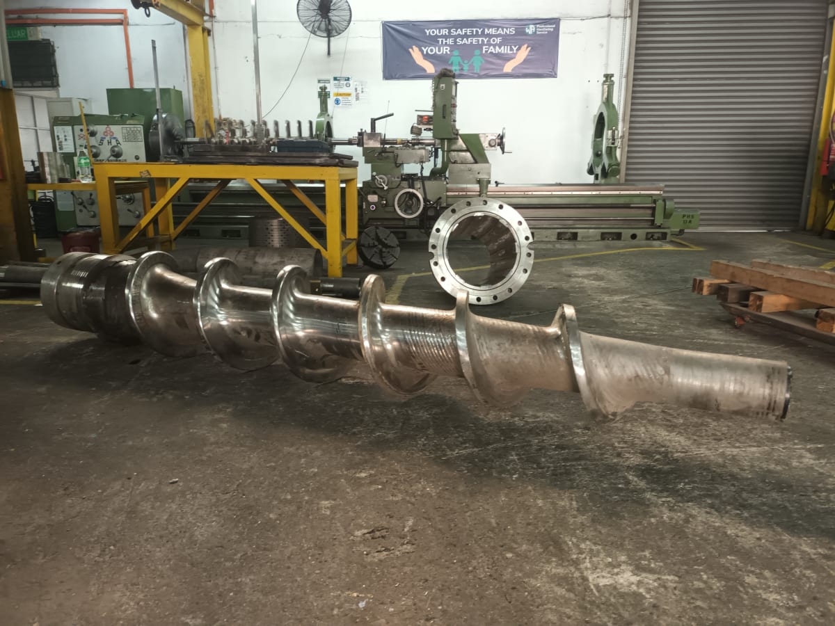
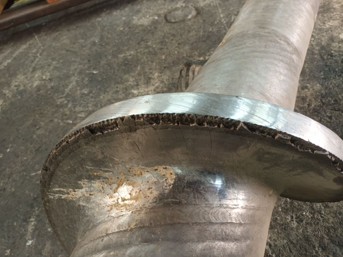
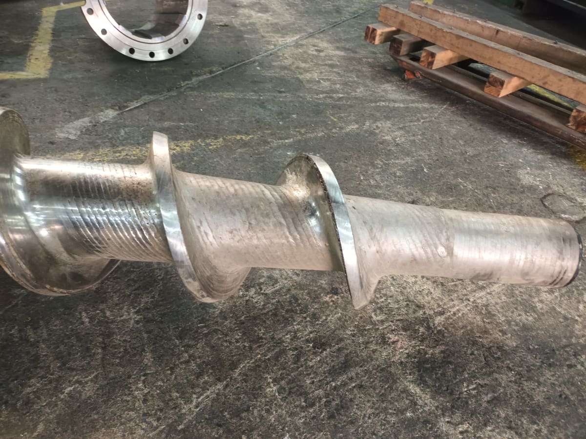
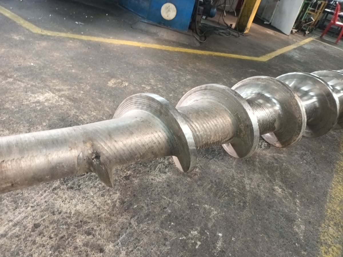
MDF Industry Process Overview: In the MDF industry, several key processes are involved in converting raw wood into finished boards. These include raw material chipping, washing and cleaning, wood chip feeding and refining, followed by forming and pressing. MDF Feeder System – Function and Importance The feeder system is a critical section in the MDF production line, primarily responsible for raw material conditioning. Its main function is to compress incoming wood chips and remove excess moisture before the material enters the cooking and refining stages. Design and Key Components The feeder system consists of several essential components, most notably the compression plug feeder screw operating within a high-pressure conical compression zone, enclosed by a wear-resistant housing. The system depends on maintaining a precise operational clearance between the plug screw flight outer diameter (OD) and the internal bore profile of the housing to ensure effective compression and dewatering. Wear Conditions and Operational Challenges Due to continuous exposure to high pressure, abrasive wood chips, and moisture-induced corrosion, this area experiences severe wear conditions. Any increase in clearance caused by wear on the screw flight OD or the housing bore directly reduces compression efficiency. This can lead to material slippage, decreased dewatering performance, and accelerated material degradation. In severe cases, it may also result in coating failures, such as tungsten carbide delamination or peeling in high-wear zones.

Industry

MDF Wood

Location

Kanchanaburi, TH

Component/Workpiece

Plug feeder screw

Business Type

Integra - Workshop

Job Type

Repair

OEM

Andritz

Type of Wear

Abrasion
Corrosion

Base Metal

stainless steel

General Dimensions (mm)

Dia 500 X 3270 mm length

Problem Description

The challenge the customer was facing

Problem Description – Plug Feeder Screw Hardfacing Failure Hardfacing Configuration The plug feeder screw is made of stainless steel, with the screw flight protected by three layers of chrome-based 431-G buffer material, followed by two layers of tungsten carbide on the flight outer diameter (OD). The front flight corner is also reinforced with a 431-G layer and tungsten carbide coating to improve wear resistance. Design Gap at Ribbon Back Face However, the ribbon back face is directly coated with tungsten carbide without a 431-G buffer layer. This creates poor bonding and low toughness at the interface, especially at sharp edges. Failure Mechanism Under high pressure, abrasion, and cyclic loading, stress concentrates at the sharp back face edge. Without a ductile buffer layer, the brittle tungsten carbide coating tends to crack and peel off. Operational Impact The detached carbide particles enter the refiner system and damage the refiner segments, leading to increased wear, reduced efficiency, and higher maintenance costs.

Previous Service Life

2y

Welding Alloys Solution

How WA solved the challenge

Recommended Solution – Ribbon Back Face Protection To prevent coating failure, the back face of the plug screw ribbon should be hardface with a martensitic hardfacing base layer to provide improved toughness and bonding strength. Alternatively, a single buffer layer of 431-G wire can be applied prior to tungsten carbide coating to enhance adhesion and reduce the risk of peeling, especially at sharp edges and high-stress

Product Category

Integra Services

Product Description

Chrome core 431-G

Technical Advantages

Technical Advantage – Improved Ribbon Back Face Protection The application of a martensitic hardfacing base material, or alternatively a single 431-G wire buffer layer, on the back face of the plug screw ribbon provides a significant technical advantage by enhancing coating adhesion and improving surface toughness. This modification reduces the risk of tungsten carbide peeling at high-stress and sharp-edge regions, thereby improving wear resistance and coating stability under severe operating conditions. As a result, it helps prevent carbide delamination, minimizes the risk of downstream contamination in the refiner system, and improves overall equipment reliability. This improvement also addresses previous customer complaints related to coating failure, eliminating the need for premature unit dismantling and reducing unplanned system downtime.

Service Life

2y

Images (4)

Photos and visuals for this case study

Case study image 1Case study image 2Case study image 3Case study image 4

Financial Impact

Solution Revenue

$38,000

Welding Procedure Specification (WPS)

1 layer(s) documented

Submission Details

Contributor

THAMEEMANSARI ABDUL HAMEED

sales@wa-phs.com

Created

April 17, 2026

Submitted

April 30, 2026

Approved By

Bastien Gerard

May 3, 2026